Latest Issue
 
Windtech International September October 2025 issue
 

Login

 Follow us at BlueSkyFollow us at BlueSky


follow


A Technical Description of the Blade Array Concept

ecowhisper
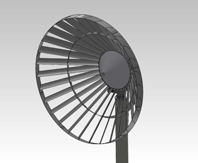
The Ecowhisper Wind Turbine (EWT) is built from a number of interdependent systems. The Blade Array interacts with the wind and its performance determines the overall performance of the whole EWT system. In this article the different interdependent systems are described.

By Stephen Thomas, Chief Technical Officer, RESA, Australia
 

{access view=!registered}Only logged in users can view the full text of the article.{/access}{access view=registered}The EWT Blade Array (Figure 1) consists of 30 forward-swept, heavily cambered blades joined by circumferential cowls at the blade tip and midway along the blade length. The roots of the blades are faired smoothly into a large diameter conical nose fairing. This combination of features reflects key aspects of the Ecowhisper design philosophy, namely maximum power production efficiency in very light winds and minimum noise at all wind speeds. A fundamental feature of wind-powered devices is that they can only produce power in proportion to the wind that is actually blowing through them at any point in time. Wind speeds are random but they generally conform to the Rayleigh probability distribution, shown in Figure 2.

The most common wind speed is approximately 4m/s (14.4km/h), which is a very gentle breeze. The reality is that for most of its operational life a wind turbine will only have light winds from which to extract power. The ability to extract power in light winds is strongly influenced by solidity, which is a measure of how ‘solid’ the set of blades appears to the wind flowing through them. High solidity turbines capture more power in light winds than low solidity turbines (ref. 1). The EWT Blade Array has high solidity (approximately 60%) as compared to typical three-bladed wind turbines, which have low solidity (5 to 7%). Consequently, the EWT will have a lower starting speed as it is able to effectively harness low wind speeds.

Having a large number of blades has also been shown to reduce noise as each blade produces a smaller fraction of the total power of the turbine. The power produced by an individual blade is referred to as its power loading. Lower power loading means that the wind is doing less work on each blade. If 30 blades produce the same total power as three blades the former will be quieter.

The Blade Array has a full circumferential tip cowl. This cowl manages the merger of the high and low pressure air flows that travel outward along the front and rear of the blade. Controlling these flows means less lost power at the tip and less noise. Aside from its aerodynamic function, the cowl is a structural item. This means that the blades are mutually supported at the tip rather than being cantilevered as is common in conventional wind turbines. This results in less noise-inducing vibration and better fatigue life. A mid-span cowl is also used to manage flow direction and provide additional stiffness to the overall Blade Array.

The blades are swept forward to suit the large diameter conical nose fairing. This arrangement of blades and fairing acts to raise the pressure on the upstream face of the blades. All wind turbines extract power as a consequence of the difference between the air pressure on the upstream face of the blade and the air pressure on the downstream face of the blade. The higher this difference, the more power is produced. Air that approaches the hub of the EWT Blade Array is diverted smoothly outwards so that it flows through the blades as illustrated in Figure 3. The pressure difference increase across the blades as a result of this concentration effect is in addition to the pressure difference generated in conventional wind turbines.

The pressure differential is further increased by turbulence generated at the sharp trailing edges of the tip, mid-span and root cowls, which reduces the air pressure behind the blades.

Wind tunnel and prototype EWT Blade Arrays used simple semi-circular section blades rolled from a flat sheet. Despite this aerodynamic limitation, Coefficients of Performance in excess of 0.4 were achieved over a wide wind speed range when these simply bladed prototypes were tested physically (refs. 2 and 3). The coefficient of performance (Cp) of a wind turbine quantifies how well it converts wind energy into shaft energy. The absolute theoretical limit for the Cp is called the Betz Limit and it is 0.59. In other words, 59% of the wind energy is the maximum possible that any wind turbine can convert. The introduction of extruded hollow aerofoil section aluminium blades is expected to significantly improve the already very good performance of the EWT. Extruded blades are also more appropriate in a production context as they are:
  • more cost-effective (near zero labour);
  • inherently of more consistent and higher quality;
  • stiffer as a result of greater and more efficient cross sectional area (increased stiffness means even lower levels of deflection and vibration).
Conventional three-bladed wind turbines have a Cp that varies between 0.1 and an absolute peak of about 0.48. Figure 4 illustrates the variation of the Cp with wind speed for a typical small three-blade wind turbine. Note that at the most common wind speed (4m/s), the Cp of this typical three-blade turbine is less than a third of the peak value.

A key competitive advantage of the EWT design is that the Cp is maintained at near peak levels over a broad range of speed. Figure 5 illustrates the minimal variation with wind speed of EWT Cp.

The EWT maintains its Cp by managing the shaft speed of the turbine. The maximum Cp at any instant corresponds with maximum power. A maximum power point tracking (MPPT) algorithm is implemented in the EWT generator controller. All wind turbines use some form of MPPT. The effectiveness of MPPT systems is widely variable. Aside from the details of the software and electronic implementations, the mechanical inertia of the rotating components and the ability of the inverter or controller to handle power and voltage spikes will dictate MPPT effectiveness. The EWT has high mechanical inertia; there are 30 blades and several cowls rotating as opposed to three cantilevered blades in a typical wind turbine. This high inertia serves to damp gust responses and helps the turbine run at speeds representative of the underlying wind speed. Turbine speed changes are smooth and consequently the controller sees less power and voltage spikes. The EWT generator controller uses a fuzzy logic type of MPPT rather than the more common and cruder 'look up table' type. Operating the Blade Array at the maximum practical Cp at all times is the key to achieving a 20 to 30% better energy harvest at common wind speeds.

The blades are bolted to the hub to enable the Blade Array to be broken down for packing in a standard shipping container.

Generator
The EWT uses a direct drive switched reluctance generator (SRG) that is integrated into the hub of the Blade Array. SRGs have been recognised as very suitable for use in wind turbines since the 1990s (ref. 5). The advantages listed then are just as applicable now: low cost, high efficiency; good control and intrinsically good response. Direct drive SRGs are particularly suited to multi kW sized wind turbines (ref. 6).

A further advantage is that the SRGs do not use high performance rare earth based permanent magnets (PM) – there are no magnets at all in an SRG. The supply situation with respect to rare earths is well documented. Rare earth PMs are experiencing extreme price escalation and volatility to the extent that quotations from suppliers of such magnets are only valid for three days at the time of writing. Aside from cost and security of supply issues, there are significant environmental, safety and durability risks associated with high performance PMs. Rare earth production results in significant quantities of radioactive waste (ref. 7). It is at odds with the green, renewable image of wind power to use a component that irreversibly pollutes the environment to such an extent in its manufacture. High performance PMs have safety risks, particularly when assembled in the quantities required for multiple kilowatt class generators. The field strength is so high that assembly of such a PM generator carries real risk of having a finger amputated and there are additional risks with respect to pacemakers and cochleal implants etc. PMs are also known to gradually lose strength, corrode with time and are not yet recyclable.

SRGs are simple devices manufactured from iron, copper and aluminium. They can achieve efficiencies as high as the best PM generators and they can do so over a broader speed/load range.

The EWT SRG is direct drive and integrated structurally into the Blade Array hub. Direct drive means that there are no gears or belts and their associated power loss and reliability compromises. The EWT SRG has a very high pole count, and is an axial gap, short flux path, four-phase external rotor type. It uses controller managed staged pole groups to boost efficiency at low load.

The EWT SRG controller features internal staging to minimise part load parasitic losses. The overall system efficiency will benefit from close integration of the generator, generator controller and inverter.

The SRG controller uses its MPPT system to constantly explore around the instantaneous operating point to ensure that the turbine is delivering the maximum power available without exceeding the upper and lower tip speed bounds that are associated with the maximum Cp. Once full rated power is achieved, the slew control system (SCS) intervenes and drives the turbine off the wind to keep turbine speed and power within the rated limits. The SRG controller MPPT and the SCS work together to maximise power regardless of wind speed. A joint general efficiency in excess of 90% is expected of the SRG and SRG controller with peak efficiency above 97%. The SRG controller has on-board data logging and is remotely programmable.

Slew Control System
The EWT has an active SCS that senses wind direction and slews the turbine to face directly into it. The SCS uses a commercial, off-the-shelf, ultrasonic sensor that measures wind speed and direction. The prototype system used a mechanical wind vane and a mechanical anemometer. These sensors were adequate but have relatively short lives at approximately 2 to 5 years. The ultrasonic sensor, by comparison, has a mean time to failure of 15 years. The information goes to the EWT SCS, which is a custom designed digital signal processor based device. The SCS also receives a turbine shaft speed signal from the SRG controller and is programmed to slew the turbine progressively off the wind once the maximum permitted shaft speed is approached. The SCS also has a number of manual overrides to enable the turbine to be incrementally slewed if required for maintenance and to enable selection of a dynamic park position. The dynamic park feature uses the wind direction sensor information to keep the turbine slewed off the wind.

The SCS physically interfaces to the pole and the turbine head assembly via a worm-geared slew drive with integrated bearing assembly. The slew drive is an off-the-shelf commercial item. It is supplied complete with a brushless low voltage drive motor which is controlled by the SCS.

The SCS is critical to the operation of the EWT and it has multiple sources of power to ensure that it is always able to control the slew drive as required. The SCS is powered by either a single or three-phase grid connection, directly from the turbine SRG, from a low voltage bus supported by the SRG controller, or by a battery back-up system. The SCS has on-board data logging and is remotely programmable.

Inverter
The EWT inverter is a four quadrant device that is designed for three-phase grid connection. The inverter can source or sink real power while at the same time sourcing or sinking reactive power. The inverter is a development of a similar device that has been successfully prototyped and field trialled.

The total kVA rating of the inverter is 5/10kVA, with a two second surge rating to over 20kVA. The output is the algebraic sum of the real (in phase) and the reactive power. This is an important and unique feature as it allows the unit to control the voltage at its point of connection. Unlike the commonly used current controlled inverters, it will not cause a rise in network voltage. In fact, the EWT inverter acts to support the local grid in the face of fluctuations caused by the connection of other distributed sources via current controlled (e.g. solar arrays, other wind turbines) and ensures that it is able to stay connected to the maximum practical extent. The EWT inverter adjusts its phase relative to the network phase to provide the small amount of power required to keep it working and to make up losses, and then adjusts its output voltage to compensate for the error in the network voltage. The inverter features internal staging to minimise part load parasitic losses. It also has on-board data logging and is remotely programmable. The inverter will have peak efficiency in excess of 98% and a broad general efficiency in excess of 90%.

Pole
The EWT is mounted to a steel hinged two-part pole as illustrated in Figure 6. This enables an 18m pole to be containerised in a standard 12m shipping container and allows the pole to be safely raised and lowered with reasonable sized cranes. The lower section is bolted to the foundation and once the upper section has been raised, it is bolted to the lower section.

An electrical junction box is located inside the lower section and accessed via a removable cover. This enables the turbine system to be fully pre-wired and tested prior to packing and shipping.

Foundations
The foundations for the EWT are site specific and depend on soil types. The default foundation is a monolithic concrete slab with a cast-in bolt nest and cast-in cable ducts.

Further Reading
  1. Numerical implications of solidity and blade number on rotor performance of horizontal-axis wind turbines, J. Sol. Energy Eng., November 2003, Volume 125, Issue 4, 425 (8 pages)
  2. Experimental investigation of a wind generator, Watkins, S., Loxton, B. and Radford, M., RMITUNIVERSITY School of Aerospace, Mechanical & Manufacturing Engineering, 9 September 2005
  3. Turbine/Electronics Evaluation, Watkins, S. and Walter, D., RMITUNIVERSITY School of Aerospace, Mechanical & Manufacturing Engineering, 7 August 2006
  4. Wind turbine generator system, power performance test report for the Whisper H40, NREL Colorado, 18 December 2001
  5. A variable-speed wind turbine based on a direct-drive variable-reluctance generator, Torrey, D.A., de Haan, S. and Childs, S.E., Windpower '94, Minneapolis, MN, May 1994
  6. The switched reluctance generator for wind power conversion, Lobato, P., Cruz, A., Silva, J. and Pires, A.J., LabSEI - Escola Superior de Tecnologia de Setúbal/Instituto Politécnico de Setúbal Rua Vale de Chaves, Estefanilha, 2914 Setúbal (Portugal)
  7. http://www.miningweekly.com/article/radioactivity-the-800lb-gorilla-in-rare-earths-room-says-lifton-2011-03-14
Biography of the Author
Stephen Thomas B.Eng. Tech (Mech) is Chief Technical Officer at Renewable Energy Solutions Australia Holdings Ltd (RESA). He has over 20 years’ experience in the successful management of product design teams through unstructured and structured project phases to deliver efficient functional economic products; his direct personal experience includes the application of sophisticated modelling tools to renewable technologies including solid oxide fuel cells, biogas digesters, biodiesel plant, desalination technologies, high efficiency generators and wind turbines.{/access}
Use of cookies

Windtech International wants to make your visit to our website as pleasant as possible. That is why we place cookies on your computer that remember your preferences. With anonymous information about your site use you also help us to improve the website. Of course we will ask for your permission first. Click Accept to use all functions of the Windtech International website.